Equipment
Contents
- 1 Equipment
- 1.1 Enquiring on Equipment Items
- 1.2 Equipment Bulk Email Changes
- 1.3 Creating Equipment Items
- 1.4 Dependent Assets
- 1.5 Equipment Reading Points
Equipment
The Equipment Register contains all relevant information about items of equipment, whether they are vehicles, buildings, rooms, etc.
Therefore the type of information held for any item must be flexible and vary with the type of item being accessed.
Enquiring on Equipment Items
Equipment Records can be viewed via two methods:
Equipment Scan Form
Equipment Tree View
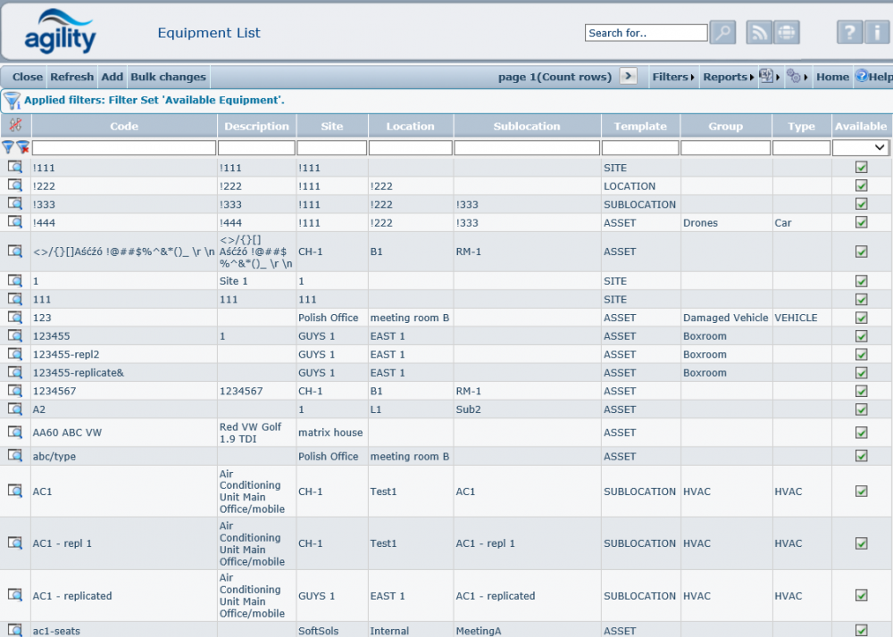
Click on the magnifying glass to the left of a record to view an Equipment item Record within the Equipment Register or select the item and click on the ‘details’ button within the Asset tree View
Equipment Scan Form
Accessed from Equipment >> Equipment List
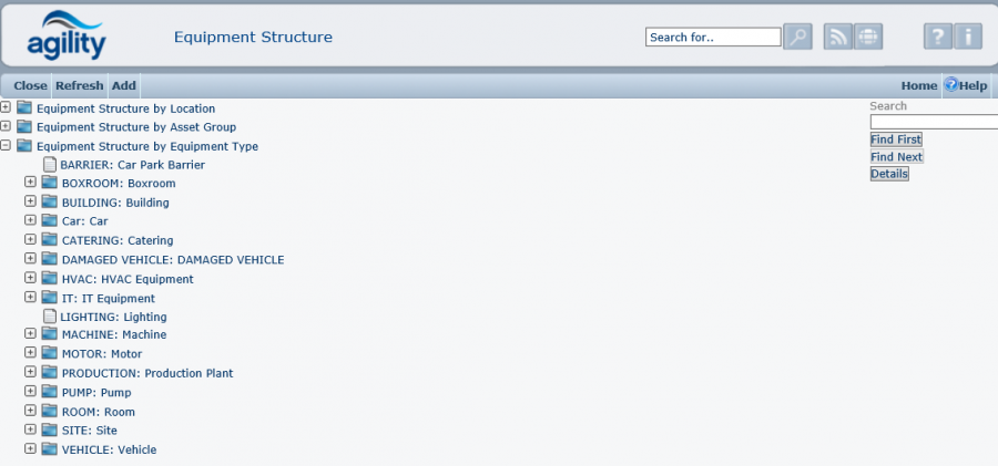
Equipment Structure Tree View
Accessed from Equipment >> Equipment Structure
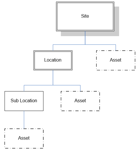
Each item of equipment within Agility may be placed into several “structures”. This feature allows you to group together items in a logical form to reflect their real life relationship. Using this structure, it is possible to place equipment items at Site, Location or Sub-Location level, as shown in the diagram below:
This structure is used to populate the Equipment Structure Tree View, which shows all available assets (those that are flagged as available and not archived):
The hierarchy structure is driven through the template field within the Equipment Detail Form.
Equipment Bulk Email Changes
This function allows the changing of email recipient data based for a selected range of equipment. So if there is a change in email address each equipment item does not have to be manually edited individually. The filter can be created as a combination of values entered by the user.
Equipment Filter
Equipment
The equipment filter allows, a single equipment items or multiple equipment items to be selected by typing part of the equipment code.
Email To/Email CC/Email BCC
This will allow filtering on a specific recipient email address, all equipment with a matching address will be returned.
Equipment group
This will select all equipment that belongs to the selected equipment group.
Equipment Type
This will select all equipment of the specified type
Location Filter
The location filter which works in addition to the equipment filter, allows equipment to be selected by site, location or sub-location.
Clicking the preview option at the top of the form then will display a list of all equipment records that will be affected by the change; the change is not committed at this point.
Example:
New Information
Once the filter criteria have been applied the new email recipient information can be entered into the new information boxes for Email To/Email CC/Email BCC.
To commit the changes click the ‘run’ option at the top of the form.
Once the run option has been clicked all equipment that meet the filter criteria entered will be updated,
Creating Equipment Items
Accessed from Equipment >> Add New Equipment
To create a new equipment item, select ‘Add New equipment’ from the main menu, or select ‘Add’ from the Equipment Scan Form or Equipment Structure Tree View. This will display a blank Equipment Detail Form.
Template
The Template field allows the user to select whether the record being created is for a Site, Location, Sub Location or Asset record. The ‘Details’ tab will change to show fields relevant to the item being created.
The default template for a new Equipment record is ‘Asset’ (shown in the diagram above).
Code
This is a unique identifying code for the equipment item. Although this code is free text, it validates that the code entered has not been input previously; you cannot have two equipment records with the same code.
Description
This is free text. A full description of the equipment can be added in this scrollable field. If there is more information in the box than can be seen then the scroll bar will activate allowing you to scroll up and down the text.
Account Code
This field is visible if system parameter "AccountCodeEnabled" = true.
Status
This is used to specify the current status of the equipment. The combo box shows only those statuses that have been set up in the Standing Data/Equipment/Asset Statuses
Details Tab
Location Box
The contents of the Location group box will depend upon the Template chosen.
The drop down lists for Site, Location and Sub Location are populated based upon existing equipment in the Equipment Register.
An asset can be defined at any level within the hierarchy. Therefore, it is only necessary to populate the fields for Site, Location or Sub-Location.
Grouping Box
Equipment Group
Select the equipment type from the drop-down list. This list is populated using values in the ASSETGROUP dictionary file. Please refer to the Dictionaries section in this document for details of how to amend this list.
This field is useful for filtering or reporting on groups of assets.
Type
Select the equipment type from the drop-down list. This list is populated using values in the EQUIPTYPE dictionary file. Please refer to the Dictionaries section in this document for details of how to amend this list.
This field is useful for filtering or reporting on groups of assets.
Contract Group
Select the Contract Group from the drop down list of Groups set up in Standing Data.
General Box
Manufacturer
Select the equipment type from the drop-down list. This list is populated using values in the MANUFACTURER dictionary file. Please refer to the Dictionaries section in this document for details of how to amend this list.
This field is useful for filtering or reporting on groups of assets.
Model
This free-format field allows for the equipment model to be recorded.
Serial Number
This free-format field allows for the equipment serial number to be recorded.
Supplier
Select the supplier from the drop-down list. This list is populated using suppliers entered in Inventory/Suppliers
Availability Box
Avail. For Work Orders?
This flag indicates if the equipment is available for work orders.
Obsolete?
This flag indicates if the equipment is obsolete. On selection of the Obsolete flag, the Obsolete Date is populated. A work order cannot be raised against obsolete equipment. The obsolete option does not remove the record from the database.
Last Updated Date
This field is updated automatically. It will update whenever the record is saved.
E-Mail Tab
E-mail notifications can be sent to pre-defined recipients whenever a work order is raised against an item of equipment. The generation of e-mails is determined within the Work Order Status Standing Data and the ‘Notifications’ System Parameter.
E-Mail
This is the e-mail address that will be used, if email notifications are operational and messages are required to go to the Address on the Equipment when the status of a work order changes.
E-Mail CC
This is the e-mail address that will be the CC recipient, if email notifications are operational and messages are required to go to the Address on the Equipment when the status of a work order changes.
E-Mail BCC
This is the e-mail address that will be the BCC recipient, if email notifications are operational and messages are required to go to the Address on the Equipment when the status of a work order changes.
Attachments Tab
Attachments
This option allows documents to be loaded against the equipment. Please refer to the Attachments section of 'Common Functionality' article in this manual for details of how to attach documents and files.
Assets Map Tab
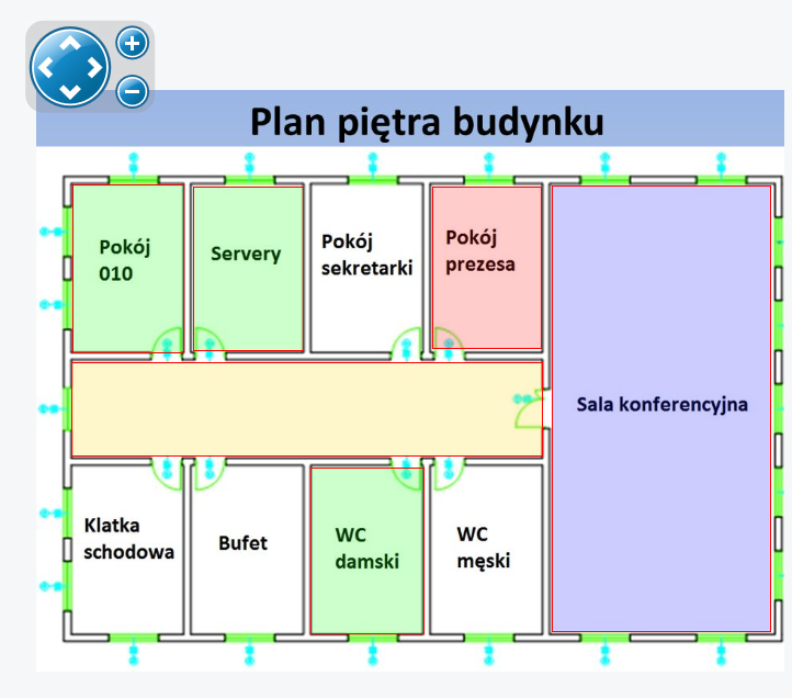
Asset Map allows to visually present location of individual assets. It can be use for example to depict a factory plan, an arrangement of machines in production line, a diagram of some device.
Uploading map
This is a standard uploading image Agility module. The image can be selected from different sources: document registry, local files, shared files and URL link. For details see Attachments section in 'Common Functionality' article in this manual.
Arranging map
After setting image there's possibility to move image up, down, left and right with arrow controls and scale up and down with + and - icons.
Creating asset links
Additional icons are used to define asset links.
![]() Pointer icon allows selecting existing asset areas. Selected area has a slightly thicker outline.
Pointer icon allows selecting existing asset areas. Selected area has a slightly thicker outline.
![]() Rectangle icon allows drawing rectangular area. To do this click somewhere on the map and drag mouse pointer from the top-left corner to the bottom-right corner.
Rectangle icon allows drawing rectangular area. To do this click somewhere on the map and drag mouse pointer from the top-left corner to the bottom-right corner.
![]() Free shape icon allows drawing more sophisticated figures. Create such shape by clicking consecutive vertices and finally click the beginning of the line to close the area. The figure cannot be created without closing line.
Free shape icon allows drawing more sophisticated figures. Create such shape by clicking consecutive vertices and finally click the beginning of the line to close the area. The figure cannot be created without closing line.
![]() Question mark is used to linking asset area with particular asset defined in Agility system. To do this select the asset area and click question mark icon. From tree structure form select asset and link will be added to the shape area. From now on clicking this area in view mode will open linked equipment details.
Question mark is used to linking asset area with particular asset defined in Agility system. To do this select the asset area and click question mark icon. From tree structure form select asset and link will be added to the shape area. From now on clicking this area in view mode will open linked equipment details.
![]() Trash bin icon is used to deleting asset area regardless if it has link attached or not.
Trash bin icon is used to deleting asset area regardless if it has link attached or not.
PPM Schedules Tab
The PPM Schedules grid will display any planned maintenance jobs that have been created against the selected equipment. “Add” button on the grid can be used to add a new planned maintenance job.
Dependent Assets Tab
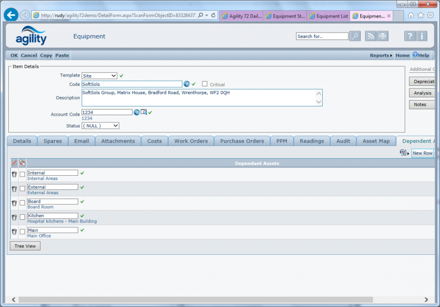
This tab is helpful to organize all the equipment that will be added to record in equipment list.
If we want to see all of them in Equipment Structure, all we have to do is click on the button “Tree View” and all of added items to record will be shown.
See section below for the details about using dependent assets in Agility.
When enquiring on existing equipment, the following additional tab folders will be available: Spares, Costs, Work Orders, Purchase Orders, Readings, Audit.
Spares Tab
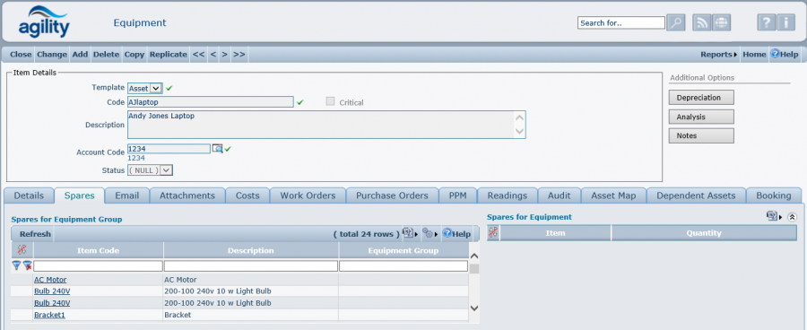
The spares tab shows all the inventory items that are used on the equipment item and asset group:
Spare parts for Equipment can be edited here. The quantity can be assigned to each spare item.
Spare parts are assigned to asset groups via the inventory items record. There is button “Add Asset Group to Items” which opens scan of all inventory items. When user opens and edit the selected item, it can add “used on” record. It will default to current asset group.
Costs Tab
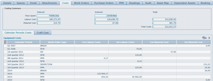
Costs are accumulated to the equipment record as soon as they are added against a task. These costs are accumulated by period and job type. They will be displayed in the Equipment Costs grid. These costs are accumulated automatically by the system therefore this grid is read only.
Work Orders Tab
The Work Order grid will display any open work orders that have been raised against the selected equipment. Additionally, any open work orders that have been raised which contain the selected equipment as a Route Sheet item are also displayed. From grid's menu it is possible to add new Work Order against this particular equipment.
Purchase Orders Tab
The Purchase Orders grid will display any open purchase orders that have been raised against the selected equipment. From grid's menu it's possible to add new direct Purchase Order to this particular equipment.
Readings Tab
Readings Tab allows viewing or entering new readings for any meter defined for the viewed equipment. See section below for the details about using meters in Agility.
Audit Tab
This tab is only visible when the System Parameter “ProcessMngt\LogAssetMovements” is set to true. This log shows all changes on fields: Site, Location and Sub-Location (movements between Sites, Location or Sub-Location).
Additional Options
Depreciation
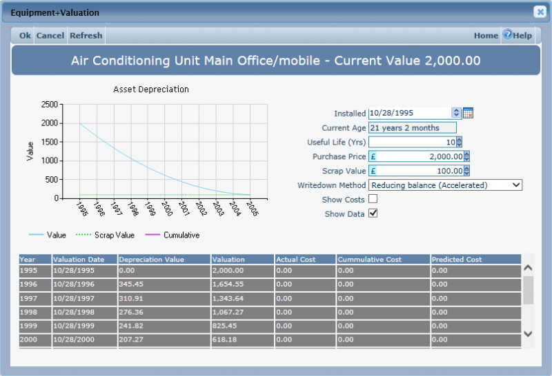
This window is used to reflect Equipment depreciation. After every changes made here hit Refresh to see actual data.
Depreciation Chart
Here will be displayed the chart based on values set in additional fields.
Installed Date
This field overwrites Installed Date field in Valuation Group on Details Tab.
Current Age
This is read-only field calculated according to installation date of equipment.
Useful Life (Yrs)
Value in years depicting span of time for which depreciation will be calculated.
Purchase Price
This field overwrites Purchase Price field in Valuation Group on Details Tab.
Writedown Method
This combo box field holds definitions of different writedown methods for depreciation calculations.
Show Costs
This flag enables/disables Costs plot in the depreciation chart.
Show Data
This flag enables/disables the grid of data with details for every year of depreciation.
Analysis
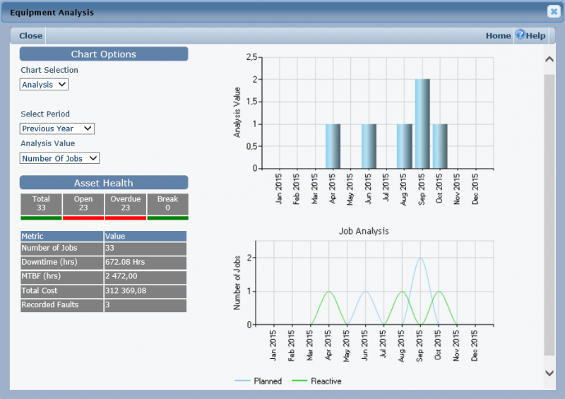
Chart Options Section
Chart Selection
This list allows to change chart type.
Select Period
This field is populated with values defined in "Chart periods For Driving Dashboards" dictionary.
Analysis Value
This field contains a list of defined values to be displayed on the chart.
Asset Health Section
This section holds statistics about jobs associated with the equipment. Every button (Total, Open, Overdue, Break) links to the Work Orders scan form filtered with adequate Status
Notes
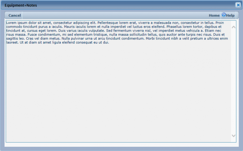
This free text field allows to make some general notes about the equipment.
Dependent Assets
The purpose of asset dependency is to help identify the effect of disabling any particular asset. The asset dependencies are stored in and viewed from a tree structure and support forward and reverse look up. They are used for enquiry and information purposes to assist in the user decision making process for undertaking work.
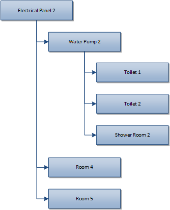
Looking at the 3 structures identified in the diagram the top level is the asset and the child items are the assets dependant on operation of the parent.
Forward Lookup
Usually the user will look from the asset down the tree structure to ascertain effects.
For example:
Using the above dependency structure we can see that by disabling ‘Air Conditioner 4’ the temperature in ‘room 4’, ‘room 5’ and ‘room 6’ will be affected.
It is also possible that dependent items will cascade but with a maximum of ten levels.
For example:
Using the above dependency structure we can see that by disabling ‘Electrical Panel 2’ the power to ‘room 4’, ‘room 5’ and ‘water pump 2’ will be interrupted. From the same structure it can also be seen that if the power to ‘water pump 2’ is interrupted then this will affect water supply to ‘Toilet 1’, ‘Toilet 2’ and ‘Shower Room 2’.
Reverse Lookup (This asset is dependent upon)
It is also possible to perform a reverse lookup. So instead of seeing which assets are affected by disabling an entity an enquiry can be made on which assets an entity is dependent on.
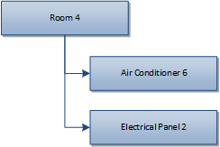
For Example:
Using the above dependency structure we can see that ‘room 4’ is affected by ‘Air Conditioner 6’ and ‘Electrical Panel 2’.
Maintaining and Viewing Structure
The dependency structure can be viewed as a tree structure, opened by a button or form link, from the asset detail screen and the request screen / work order detail screen (in the context of the asset that the request has been raised against). Viewing the structure shows the complete dependency tree, this is presented to the user as a tree view. The number of levels displayed will not exceed 10.
Maintaining
The dependency structure is maintained from the asset detail form by adding one level of child assets / equipment items that are dependent on the currently selected asset.
The asset dependency form launched from the asset detail is split horizontally into 2 panes. The left pane shows the current tree view in forward lookup. The right view shows a list of the child assets and equipment items that are dependent on the currently selected asset.
New child items are added by selection from a list, or removed using the delete selected rows function. When the list of items is modified the tree view panel is automatically refreshed to show the uncommitted changes in structure.
Viewing
The dependency structure is viewed as a tree view only when the structure is viewed from the request / work order form. This is presented to the user in the same manner as the ‘equipment structure’. With the exception that an extra button is made available in the controls that changes the view to a reverse lookup on the currently selected asset. When viewing structure from the asset, the maintenance form is used in enquiry mode.
Equipment Reading Points
Reading points (meters) can be defined and associated with equipment items. The purpose of a reading point is to allow the recording of readings to be made and stored against the associated equipment item with a date and time stamp. A work order number can optionally be stored with the reading. The stored reading data can then be used for predictive maintenance and monitoring of equipment using charting. Reading points can be set up as part of the Standing Data Process or alternatively they can be added when adding New Equipment. Reading points can be accessed from
- Equipment detail, using the readings tab
- Work order detail, using the readings tab
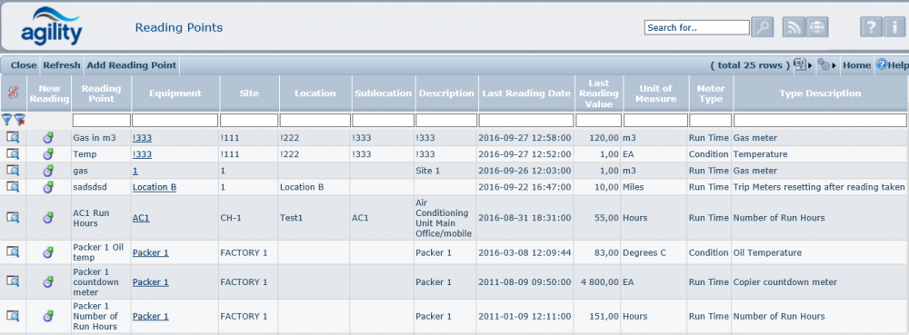
- Directly from the menu Equipment >> Reading Points
- Standing Data
Enquiring on a reading point opens a scan form.
Equipment
Equipment, the Reading Point is being defined against.
Site / Location / Sub-Location
The site, loaction and sub-location of the equipment item where applicable.
Description
The free text equipment description.
Last reading date
The date and time of the last reading taken.
Meter Type
Select the meter type from the list of defined Meter Types (see Standing Data: Equipment -> Meter Types for more information about Meter Types)
Unit of measure
This is the unit of measure for the meter, taken from the meter definition.
Meter Type
The type of meter, this is either a runtime or a condition value
Note that it is necessary when adding a new reading point to create the first reading, which is not necessarily 0.
Control Records (Run time PPM)
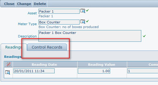
Each reading point can have associated control records. This is accessed from the control record tab on the reading point details form.
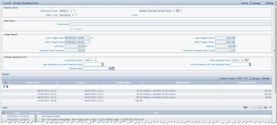
The control record contains all attributes for the generation of PPM jobs based upon usage and is used as the reference point for generation. It also contains a log of jobs generated as well as a log of usage.
Multiple control records can be held against each reading point allowing the generation of PPM jobs on different cycles.
The form also contains functionality allowing a reading point to be changed whilst maintain the run time history.
Reading Point Box
Equipment Code
The equipment code of the equipment the reading point is associated with
Meter Type
The type of meter, (see Standing Data: Equipment -> Meter Types for more information about Meter Types)
Reading point
This is the name of the reading point.
Unit of measure
This is the unit of measure for the meter, taken from the meter definition.
Description Box
Comments
Free text field for adding additional information about the reading point.
Active
Check box determining if this particular control record is active. If the control record is not active then PPM’s will not be generated from this control record.
Usage Based Box
Last Trigger Date
Last Date/time at which a PPM was generated from this control record
Next Trigger Date
Next Date/time at which a PPM will be generated based upon usage.
Life Time
This figure represents the overall life time of the equipment to which this reading point has been associated.
Example:
Using a car and gearbox scenario;
If we have 2 cars, one has done 20000 miles and the other 30000 miles. We also have a brand new gear box. We fit the gear box to one car and do 10,000 miles in the car, the gear box is then swapped to the other car. The car containing the gearbox has done 30000 miles but the life time reading of the gear box would still only be 10000. So the PPM to service the gearbox would still be based upon the gear box usage and not the car containing it.
Last trigger value
This is the value at which the last PPM job was triggered
Next Trigger value
This is the value at which the next PPM job will be generated
Interval
This is the factor that determines when a job is triggered. The figure represents the cycle in the unit of measure at which to generate a job.
So for example if we have an interval of 100, every time the usage reaches or exceeds intervals of 100 a job will be generated.
Forecast Daily Average
This figure represents a calculated average value of the amount of usage for each day.
Forecast Average Days Cycle
This figure represents the value in number of days, based upon usage, at which the interval will be hit and a job triggered.
For example if the interval was set to 100 and usage was 100 per day then this value would be 1.
Change Reading Point
The change reading box allows a reading point to be changed for a different one but still maintain the run time history for the equipment item to which the reading point has been associated.
Equipment Code
The equipment code to which the reading point is to be associated
New Reading Point
The new reading point to be associated with the equipment item
Last Reading of Current Reading Point
This is the last reading taken of the existing reading point prior to it being removed from the equipment item.
Current Reading of New Reading point
This is the reading of the new reading point taken when the item was attached to the equipment item but prior to any usage.
Change Date
This is the date at which the change took place so that new readings are taken from this date onwards.
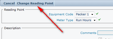
To change the reading point click the ‘Change Reading Point’ Option in the toolbar, following details being entered.
Two logs are maintained at the bottom of the form, and these are displayed as grids.
Usage
The usage grid shows usage by show the period between the pervious and current reading point and the reading value.
From Date
This is the will be the date the last reading was taken. (or the previous ‘to date’)
To Date
This is the date the reading was taken and forms the ‘from date’ of the next reading.
Usage Value
This is the meter reading that was entered on the ‘To Date’ and represents the usage for the period ‘From Date > ‘To date’
Meter Point
The name of the reading point
Logs
This displays a time and date stamped activity log of this particular control record in reference to the PPM. Showing when the PPM was triggered, when run time values were re-calculated and changes to the control record.
Adding Readings
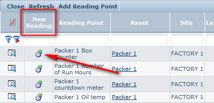
New readings can be added to the reading point using a separate form which is launched by clicking Add icon in the ‘Reading Points’ (see reading points for more information) scan grid.
Readings can also be added from these following locations.
- Equipment Details, using the readings tab
- Work order details, using the reading tab
- Standing data, using the reading points detail form in change mode
The captured reading information remains consistent.
Action
This is the type of reading to be added, select the appropriate type from the drop down box.
Reading.
This is the most commonly used for entry of readings, except where a specific action needs to occur for example a reset.
Reset
Used when the real run time counter is changed so actual reading can be lower than last.
For example;
A machine has a component that requires service every 10,000 uses, and a life span of 100,000 uses. When 100,000 uses has been reach and a new component fitted the counter could be reset back to zero so that the number of uses is maintained accurately.
Roll Over
This is used to enter a run time reading that exceeds the minimum or maximum value entered for a meter basically allowing the meter to exceed the maximum.
Comments
Optional free text description of the reading
Job
Optional Job number if taking the reading was a part of the Job.
New Reading Box
Reading Date
This is the date and time the reading was taken.
Value
This is the reading value.
The previous reading date/time and value is displayed for you convenience and also allows checking that the new reading is sensible.
Backdated Readings
Backdated readings can be entered between two entered readings; or as first reading only.
Such readings will not affect the total value of reading point, and will not update related run times.
Modifying existing readings
It is possible to only modify the last reading entered against a reading point. When the new reading is entered it is checked for validity, to ensure for example that the revised reading entered is not lower than the previous reading entered.
